Deciphering the RS-232 Port on Iskra Delta Partner

Iskra Delta Partner is a series of personal computers that were manufactured in Yugoslavia in the 1980s. In this blog post, we will explore how a Partner (specifically, the "GDP" version) can be connected to a PC using a serial connection.
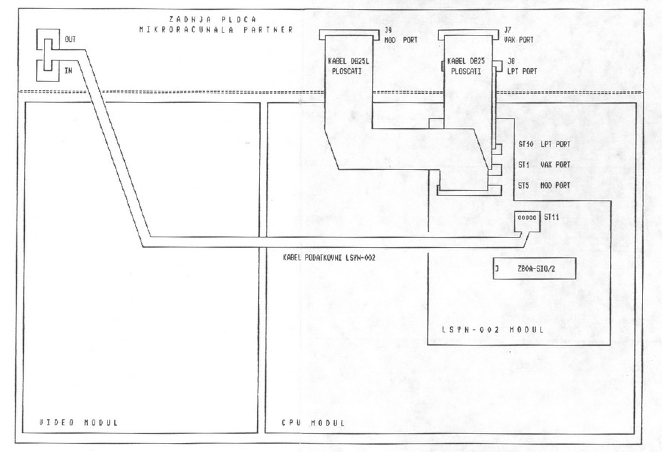
First, let's take a look at how the I/O channels of Iskra Delta Partner are described in the IDP User's Manual. All versions of Partner come with at least one RS-232-C serial port called "LPT," which is meant to connect a serial printer. This connector is supposed to be labeled "J7" on the back of the computer. Extension option 1 includes two more serial channels (which are the same as LPT): "VAX," labeled as "J8," and "MOD," labeled as "J9." Extension options 2 and 3 include a parallel port with binary input-outputs, called "CEN," and labeled as "J6" on the back of the computer. Option "Lsyn 0002" extends Partner with a synchronous communication channel, and option "LAN" enables a local network between Partners. A special software package needs to be used for the last two options to work.
Our Partner has an I/O card which provides 3 I/O channels. The card itself is named "LAN" and "comes with" a manual called "Communication Adapter LSYN-002". It is not yet clear which of the above extensions are implemented with this card, but most likely it adds options "Lsyn 0002" and "LAN". Looking at this Manual, it becomes apparent that the LPT RS-232 port is labeled as "J8" (and not as "J7") on the back of the computer if this card is installed. So, our best bet is to connect to the "J8" port.
The IDP Manual explains how the ports can be configured. Specifically, there are logical I/O channels (CON, AUX, LST) and physical I/O channels (GDP, CRT, LPT, VAX, MOD, CEN). The CP/M command "DEVICE" can be used to tie a logical channel to a physical channel and also set the communication parameters (such as flow control and baud rate). The command is used as follows: DEVICE logical-channel:=physical-channel[parameters. For example, DEVICE AUX:=LPT[x,1200 ties the logical channel "AUX" to the physical channel "LPT" and sets the flow control to XON/XOFF and baud rate to 1200 bauds per second.
The User's Manual suggests using the "RMT20" program to utilize Partner as a terminal. The manual hints that RMT20 communicates with a remote computer through the AUX logical I/O channel. This led us to connect a [female] DB25 connector to the LPT port, configure the AUX channel, and test if RMT20 transmits something over the transmit line.
To set up the connection, we soldered two wires to the DB25 connector, one to pin 2 (TX, transmit) and the other to pin 7 (GND, ground). We then plugged this connector to "J8" on Partner. Next, we attached an oscilloscope to the two attached wires. We assigned the LPT physical channel to the AUX port and disabled hardware flow control by setting it to XON/XOFF using the CP/M command DEVICE aux:=lpt[x,1200. We found the RMT20 program on the hard disk provided with the emulator (GRMT20.COM). When pressing keys on Partner's keyboard, we were able to detect, with the oscilloscope, that characters were being transmitted over the TX line.
Since our PC did not have a serial port, we had to use a USB-to-Serial adapter. The adapter had a female DB9 connector on one end. We attached the two wires coming from the Partner to a male DB9 connector, with one wire connected to pin 5 (GND, ground) and the other to pin 2 (RX, receive). Next, we attached the USB adapter to the PC and configured a terminal program to match the AUX/LPT settings on the Partner. We discovered that we needed to set the baud rate to twice the setting on the Partner for it to transmit correctly. With this setup, we were able to receive data on the PC.
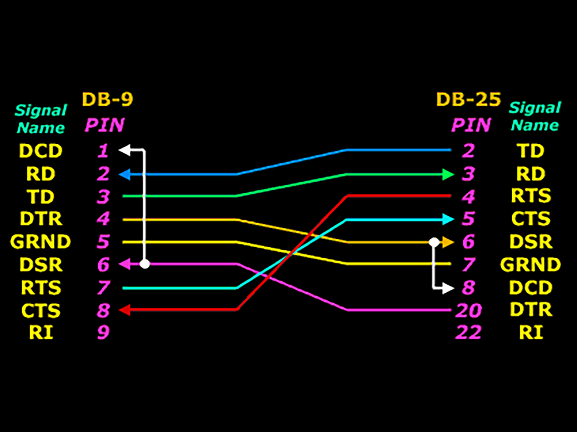
We ended up creating a full-blown null-modem cable. However, we discovered that the DTR and DSR signals are not supported by IDP, which means that we had to set the PC terminal to RTS/CTS hardware flow control when switching the Partner to "hardware flow control".
After successfully establishing communication, our next step was to be able to do the same thing from within our own program running on the Partner. To get started, we decided to look at how GRMT20 sends a character to the PC. Using the emulator, we were able to trace the program and locate the following piece of code:
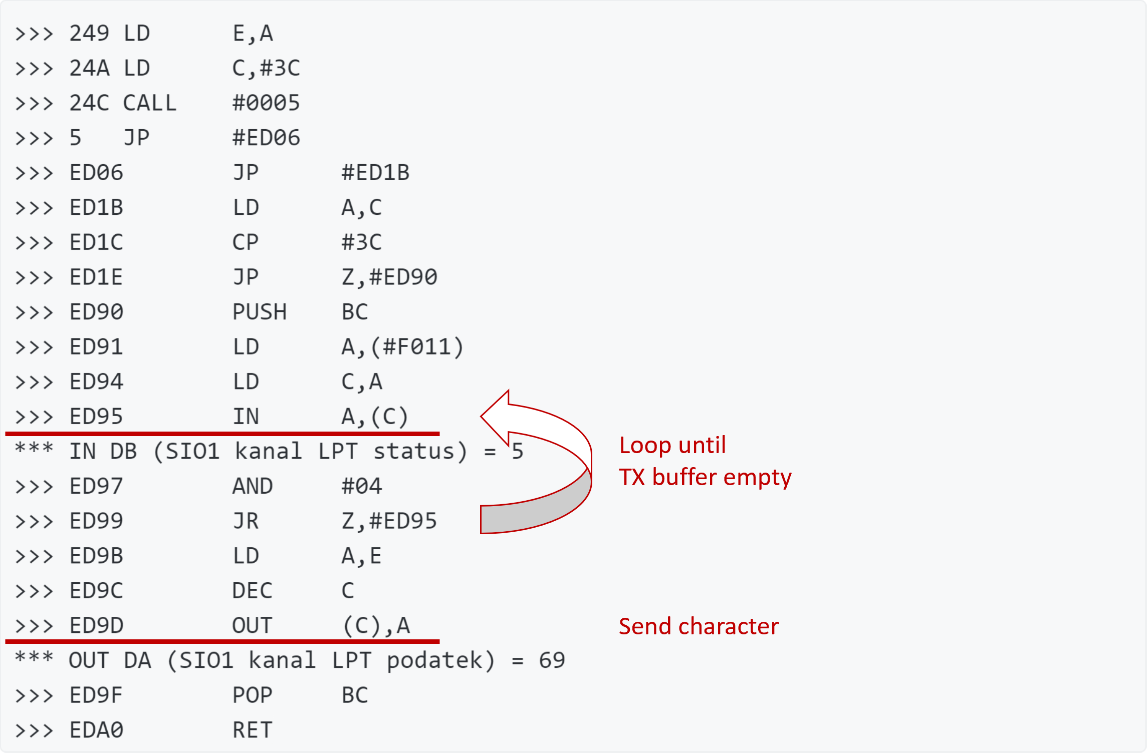
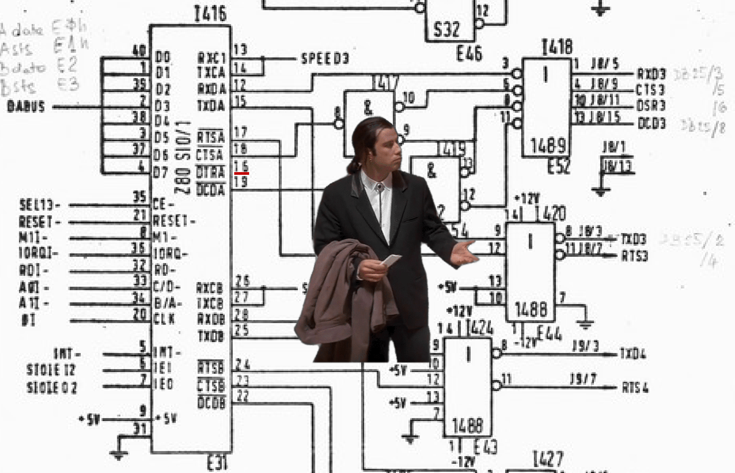
We were able to use this code to send a character to the PC, but only after running GRMT20 first and breaking out of it with Shift+Break. This suggested that GRMT20 initializes the Z80 SIO chips that are used by IDP for serial communication. Upon further investigation, we discovered that GRMT20 extends BDOS with SIO-related functions and installs its own interrupt handlers. While this may have been a viable solution, it seemed too messy for our liking, so we decided to refer to the Z80 SIO documentation instead (this or this).
IDP has two SIO chips, each supporting two channels corresponding to CRT, LPT, VAX, and MOD, respectively. We were using channel B on the first SIO chip (LPT), and we had to make sure not to break the keyboard that was using channel A on the same chip. Interestingly, disabling the "Status Affects Vector" option on channel B can actually break the keyboard, since this setting affects both channels. Similarly, setting the interrupt vector also affects both channels and can have the same effect.
By initializing SIO correctly, we were soon able to send a character to the PC. With this accomplished, we moved on to receiving characters and creating a full-blown polling loop. Since interrupts can bring in all sorts of trouble, we decided not to utilize them in the first step. Nonetheless, we explored interrupts to set the groundwork for using them later in the project.
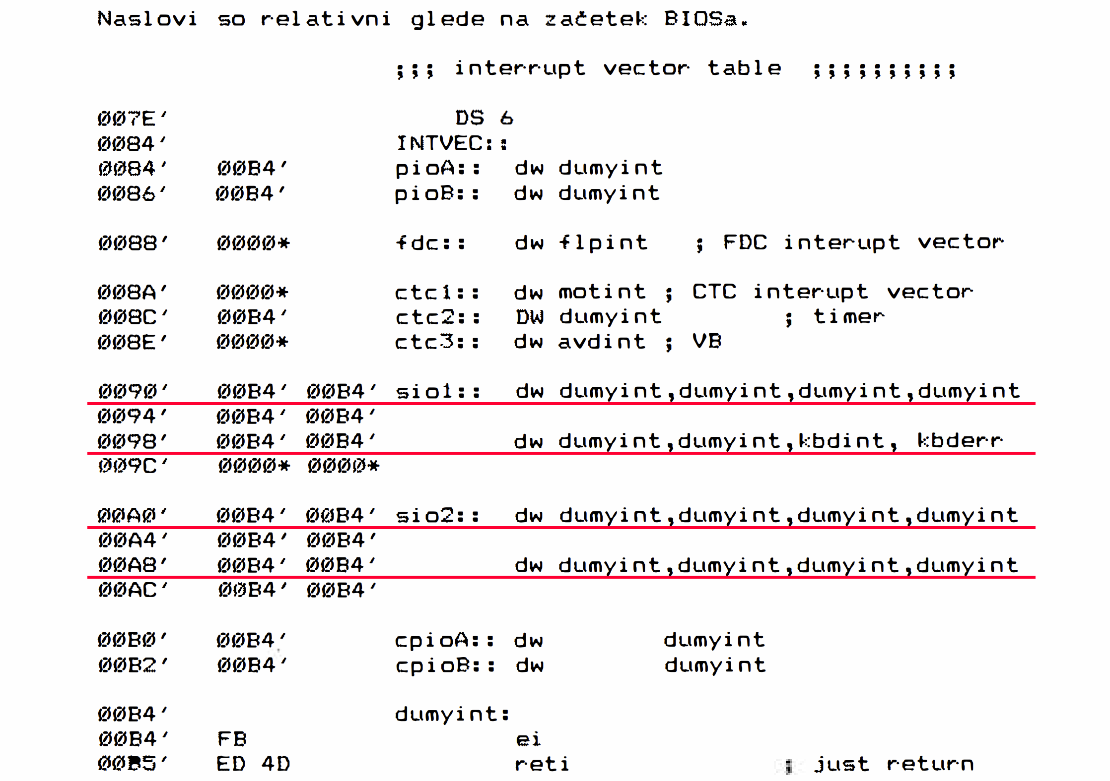
The IDP interrupt vectors for the SIO channels are as follows:
- Chip 1, channel B (LPT): 90h
- Chip 1, channel A (CRT; keyboard): 98h
- Chip 2, channel B: A0h
- Chip 2, channel A: A8h
These addresses are offsets from the start of BIOS. To obtain the BIOS address, we need to read the memory at 0001h and subtract 3 from that. On our Partner, that's FA00h.
Interrupt handlers and the buffers used by the handlers must reside in the shared memory space because they can fire when either of the two memory banks is enabled. The shared memory space supposedly starts at C000h and goes to FFFFh, with BDOS starting at F400h. Further tests are needed to validate this. The space available for handlers is thus from C000h to F400h. However, other interrupt handlers and their data may be installed here, so we must be careful not to overwrite them. The keyboard handler is at FEA7h (inside BIOS, which is good as we will not interfere with it). GRMT installs its SIO handlers at EE9Ch and EE81h (and we most likely should do the same).
When utilizing interrupts, certain functions must be put into "transactions" and not allow the interrupt handlers to execute while they are executing, especially when addressing the SIO registers. We are not yet sure whether this can be achieved simply with DI-EI or whether something more elaborate is required.
As you can see, interrupts pose several challenges. We are not yet sure if these outweigh the benefits. However, we will explore this further as it represents a good challenge and will uncover a lot about how IDP interrupts work.
In conclusion, we were able to establish a successful serial connection between an Iskra Delta Partner and a PC. We were able to configure both the physical and logical I/O channels for initial testing. Despite encountering some hurdles, we managed to implement a serial communication library for IDP. In addition, we delved into the Z80 SIO documentation and gained a deeper understanding of the Partner's serial communication system. Last but not least, we laid the foundation for extending the library with interrupts in the future.